
This ITRC Technology Information Sheet describes passive sub-slab venting systems for mitigation of vapor intrusion (VI). Passive venting systems differ from sub-slab ventilation (SSV) systems in that the former are not electrically powered and rely on temperature and pressure differences between the building and atmosphere to induce airflow. A brief overview, along with advantages and disadvantages, is provided below. |
Overview
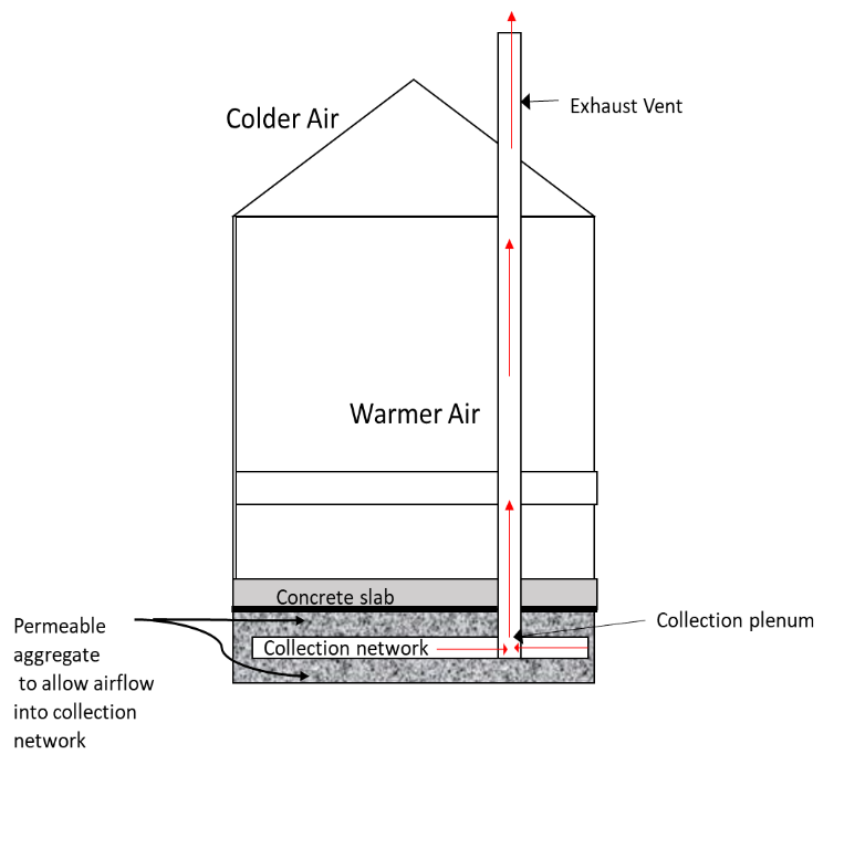
The goal of a passive sub-slab venting system is to vent to the exterior atmosphere contaminant vapors that have accumulated beneath a structure. Combined with a passive barrier, contaminant vapors are captured and rerouted through a passive venting system to prevent contaminant vapors from entering the building and accumulating within the indoor air environment.
Passive sub-slab venting systems rely on wind effects, thermal effects, and pressure differences to induce airflow. This airflow moves contaminant vapors, which may accumulate beneath a building, through vents to the atmosphere. The amount of venting attributed to natural airflow and the resulting vapor concentrations below the passive barrier depend on site-specific conditions and the resistance of the venting material or the subsurface to air flow. A passive venting system is most easily installed prior to building construction. While effective passive venting systems have been designed for existing structures, their effectiveness relies on the presence of a permeable subsurface layer and the ability to install an adequate network of conveyances for venting along with an adequately sealed floor slab. Passive venting of existing structures is often limited by the permeability of the sub-slab materials and the lack of a perforated pipe or vent strip conveyance system. Therefore, passive venting is most commonly used in new construction. A typical way to vent sub-slab soil gas in new construction is using a perforated ventilation network, consisting of pipes or low-profile vents that run beneath the slab and direct the vapors to a centrally located plenum box or pipe header. Another effective sub-slab ventilation option is an aerated floor void space system (VSS); details of a VSS are provided in the Aerated Floor Void Space Systems (VSS) Technology Information Sheet.
Existing structures may be retrofitted with passive venting systems using vertical vent points installed through the floor slab, or by installing a network of horizontal vent piping trenches constructed beneath the existing floor slab. This approach requires modifications and repairs to the existing concrete floor slab.
Passive sub-slab venting systems are generally used in conjunction with passive barriers. The venting system reduces contaminant concentrations in soil gas beneath the barrier and the potential impacts of vapor migration through barrier conduits into a building. Passive barriers improve the capture efficiency of a venting system by eliminating air flow between the interior of the structure and the vented space (see also Passive Barrier Systems Technology Information Sheet). Passive barriers also prevent vapor entry when passive venting systems are not evacuating air from the sub-slab environment (e.g., during high atmospheric pressure or when there is little to no air flow). When passive venting systems are used in conjunction with passive barriers, the collective systems are referred to as passive sub-slab vapor intrusion mitigation systems (VIMS). Some passive venting systems are designed to introduce ambient air into the network to dilute contaminant vapor concentrations prior to discharge to the atmosphere. This is accomplished by installing dilution header pipes that collect ambient air from areas outside of the contaminant zone or building envelope. Inclusion of dilution piping is more common in passive vent systems for new construction where more space is available to install the dilution pipe headers.
Passive sub-slab venting systems differ from sub-slab depressurization (SSD) systems (as described in the Sub-slab Depressurization Technology Information Sheet) in that passive systems may not create a measurable or consistent pressure differential across a slab. Performance metrics should focus on evidence of airflow in the vent and riser piping rather than pressure measurements. Measurement and evaluation of vapor-phase contaminant concentrations in the sub-slab and indoor air environments are other performance metrics used to evaluate the efficiency of a passive VIMS.
Following system installation, post-installation verification should be conducted to document that flow is not obstructed through the system. Refer to the Post-Installation Verification Checklist for a complete list of system construction and operational parameters to monitor following installation. Operation and maintenance of a passive sub-slab venting system is generally limited to periodic verification of flow through the riser pipes and monitoring. Refer to the Operation, Maintenance, and Monitoring Process/Exit Strategy Fact Sheet and Operation, Monitoring and Maintenance (OM&M) Checklist for more information on OM&M of passive sub-slab venting systems
Source: S. McKinley, used with permission.
Components
Passive sub-slab venting systems for new construction consist of a network of horizontal vent piping surrounded by a layer of permeable fill material below the concrete slab or foundation of a building. The vent piping may consist of perforated pipe or low profile-venting material, which is a highly permeable strip of geotextile matting (see Figure 3). The lateral vent pipes or low-profile vent material are connected to vertical vent piping that routes contaminant vapors through the building to the atmosphere. The fill material surrounding the vent piping or low-profile venting below the concrete slab must be permeable enough to allow for adequate flow of air and contaminant vapors into the horizontal vent piping or low-profile vent material.
Pressure differences and airflow rates within a passive vent system will be dramatically lower and more inconsistent than in an active system with a fan. Therefore, passive systems require a well-connected network of slotted or perforated piping or low-profile vents, a permeable sub-slab layer to allow airflow into the piping, a competent seal between foundation and walls, and a competent slab to minimize leakage. Compared to an active system, passive systems may require multiple collection points, a more extensive horizontal network of vent piping, and a collection plenum or header to be effective. The basic system components shown in Figures 1 and 2 include:
- high permeability material beneath a competent slab or barrier (e.g., AASHTO M 43 No.57 or 67 stone). See Figures 2 and 3.
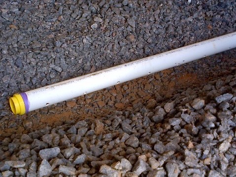
- venting network of slotted/perforated collection pipes, low-profile vent material, or aerated mats beneath the slab. Schedule 40 polyvinyl chloride (PVC) or standard dimensional ratio (SDR) 35 slotted or perforated (factory- or field-drilled) pipe is typically used for vent piping. See Figure 4.

Source: S McKinley, used with permission.
Source: CETCO
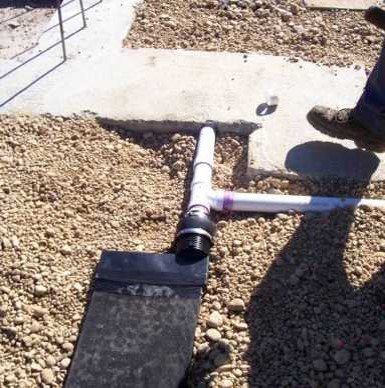
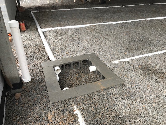
- collection plenum box, typically constructed of hollow concrete blocks turned on their sides with an empty space in the center. It vents the sub-slab collection system to the outside atmosphere through a vertical riser. A pipe header can also be used to connect the vent piping to the riser. See Figure 5.
- impermeable barrier as necessary to provide continuous protection from vapor entry between the slab and venting network. The barrier should be resistant to the site contaminants of concern (COCs) and adequately sealed; typical moisture barrier or even radon barrier systems may not provide necessary chemical resistance. See Figure 2 and refer to the ITRC Passive Barrier Systems Technology Information Sheet for more information.
Source: A. Rodak, Duncklee & Dunham, used with permission.
- exhaust vent(s), which are riser pipe(s) that extend through the slab, roof, or wall of the structure to the outside. Most of the riser pipe length must be in a conditioned area so that the warmer air inside the pipe will rise through the structure and vent the subsurface through thermal venting. See Figure 1.
- design components, such as fans and associated controls, to upgrade to active mitigation if necessary. See the ITRC Sub-slab Ventilation Technology Information Sheet.
Advantages
Because passive sub-slab venting systems do not have a fan, they reduce the risk of mobilizing soil gas to the vent riser stack, which would create a point source for outdoor air contamination. In addition, passive sub-slab venting systems offer several other advantages:
- Users avoid long-term costs for mechanical part maintenance and operation.
- They have energy-efficient function (i.e., green and sustainable technology).
- This type of system does not rely on a power source for continuous operation.
Source: Duncklee & Dunham, used with permission.
- Depending on the permeability of subsurface soil, passive sub-slab venting systems can often capture vapors over a large surface with minimal pipe coverage area.
Limitations
Compared to active venting, passive systems may not be able to reduce concentrations of sub-slab soil gas COCs to less than regulatory screening or indoor air quality levels over the same time period. Other limitations of passive sub-slab venting systems include:
- They may show reduced performance, when compared to active systems, due to the absence of an electrical fan or blower to induce continual airflow and by stack effects that are more influential in cooler weather periods
- Effective coverage area of each riser pipe may be limited. Passive venting systems tend to “breathe” in and out, and therefore vapors cannot travel great distances without the use of an electrical fan or blower.
- Performance may depend on the integrity and life of the seal above the sub-slab venting system.
- Performance may be affected by building foundation settlement.
- Presence of concrete footers or sub-slab wall extensions may require additional vent piping
- Some states may not allow passive venting systems.
- An effective system may require a larger number of riser pipes than active systems.
Cost Considerations
- Incorporating passive sub-slab venting systems into new construction will be less costly and more effective than in existing construction.
- Typical installed costs for a new construction passive venting system vary widely depending upon materials used, but typically range from around $3 per linear foot for low-profile vent materials and around $8 per linear foot for slotted PVC pipe. This range does not include cost for a barrier and the permeable layer.
- Use of collection plenums may reduce the number of horizontal pipe sections or overall pipe length.
- The type of riser pipe used on the interior of the building affects cost. PVC riser pipes are more economical; however, more expensive cast iron vent riser pipes may be required to meet local building code requirements or to prevent damage post-installation.
Special Circumstances
- High water table or an impermeable sub surface may limit venting effectiveness and prevent use.
- Isolated areas under elevated or noncontinuous slabs should be addressed by placing adequate gravel below these areas and adding additional ventilation pipe to the passive venting system.
Occupant, Community, and Stakeholder Considerations
It is essential to develop and implement a site-specific community involvement plan that addresses, among other things, how to win trust and gain access to properties, communicate risk to potentially exposed individuals and minimize the disruption of people’s lives and businesses. For more details, see the ITRC Public Outreach During Vapor Intrusion Mitigation Fact Sheet.
Resources
Related Links:
- EPA Engineering Issue: Indoor Air Vapor Intrusion Mitigation Approaches, EPA/600/R-08-115 October 2008
- Guidance Document for the Vapor Intrusion Pathway, Michigan Department of Environmental Quality, May 2013
- NAVFAC: Vapor Intrusion Mitigation in Construction of New Buildings Fact Sheet
For more information and useful links about VI pathways and mitigation technologies, go to http://www.itrcweb.org .

[email protected], 919-707-8279 Matthew Williams, Michigan Dept. of Environment, Great Lakes, and Energy [email protected], 517-881-8641 |
Click here to view a PDF version of this Tech Sheet.

