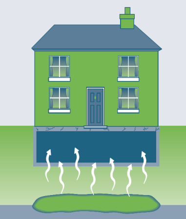
This ITRC Technology Information Sheet provides basic information when using a fan to depressurize soil or a small air space below a sealed membrane barrier, usually placed on the exposed dirt floor of a crawlspace (or dirt floor basement) to mitigate potential vapor intrusion (VI) into a building. SMD is a common engineering control used for buildings at or near VI sites. Although this technology is more commonly applied to residential buildings (due to building construction features that create spaces where SMD can be used), SMD can also be used in commercial and industrial buildings. Depressurization occurs when a negative pressure differential is extended below the installed membrane relative to the indoor air space above the membrane. |
Overview
SMD is a commonly used engineering control for mitigating VI in buildings that are built over a crawlspace-style foundation. SMD may also be applicable for dirt floor basements and basements with compromised concrete floor slabs with consideration to whether frequent access to these spaces are needed. The types of fans/blowers used for SMD vary, depending on the size of the area, how well sealed the membrane is, and the size and age of the building requiring mitigation. SMD relies on the ability to access and install a durable membrane over the exposed soil (or slab, in some cases) in the crawlspace/basement that enables a negative pressure to be generated below the membrane. Prior to placing and sealing the membrane, a venting mechanism (e.g., perforated pipe, geocomposite soil gas collection mat) should be installed and connected to a vertical section of solid piping,
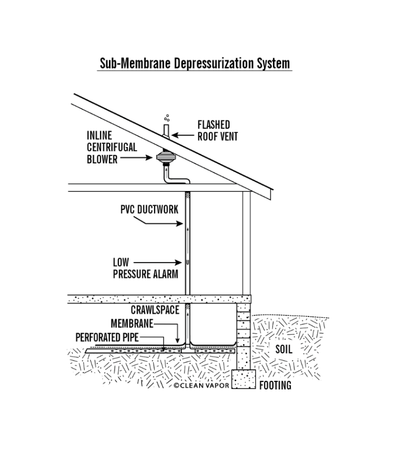
Source: Clean Vapor, LLC, used with permission.
leading to a fan mounted exterior to the occupiable building envelope. The vertical section of pipe should convey soil gas to a discharge point above the roofline and away from building openings. Following installation and commissioning, performance of the SMD can be measured by collecting differential pressure readings from below the membrane relative to the area and/or building indoor air.
Components
This technology requires a fan or blower connected via piping to the space directly below the membrane (see Figure 1). The electric fan or blower can be installed on either the outside or inside of a building, depending on access and the locations available. Typically, fans are installed on the outside of the building due to access issues, both for system installation and for ongoing system operation, maintenance, and monitoring (OM&M). Fans installed on the outside of a building are subject to changing weather conditions and, depending on the geographic region, may experience condensate issues and/or additional wear on the fan. Fans installed in interior spaces (for example, attics) must be fully excluded from occupied and/or insulated interior spaces (i.e., fans need to be located outside the occupiable building envelope) to mitigate the potential for leaks in the fan’s vent from entering the occupied space. Fans installed in protected spaces, such as attics, have a longer and more consistent operating life because they are protected from extreme weather conditions, but also require access to be granted by the property owner and occupants for each OM&M visit. Qualified personnel should oversee the design, installation, and OM&M of SMD systems.
Other features of an active SMD system may include:
- system piping, including a sampling port for conducting system diagnostic testing (i.e., vacuum and air velocity/flow) and sample collection for analysis of VOC concentrations in effluent or sub-slab vapor flux concentrations
- permanent u-tube manometer, vacuum gauge, or pressure sensor on the system piping to monitor system pressures
- balancing valves on the system piping, which allow adjustments to system flow when installing multiple suction points through the membrane, when multiple crawlspaces or multiple basement areas are present, and/or when combining SMD with sub-slab depressurization (SSD) or other active mitigation methods. Balancing valves may help reconfigure the system footprint as vapor concentrations diminish over time. Blowers that have variable speeds may also be used to balance or rebalance a system over its operational life.
- monitoring points through or below the membrane, for the purpose of monitoring the extent of the vacuum. At least one port should be located distant from the applied vacuum point to verify influence at remote extents.
Advantages
SMD as an active mitigation technology has the following advantages:
- SMD is a readily deployable engineering control.
- This is a cost-effective mitigation method for crawlspaces and preferred over crawlspace ventilation (CSV) if access to the crawlspace is possible. See CSV Technology Information Sheet for more information.
- SMD generally allows use of lower-vacuum, in-line radon fans to achieve SMD.
- Installing and sealing a membrane barrier makes it less likely in comparison to a CSV system that indoor air will be drawn down into the crawlspace.
- Performance can be reliably monitored through telemetry connected to sub-membrane monitoring point(s).
Limitations
SMD as an active mitigation technology has the following limitations:
- A thorough health and safety evaluation should be completed, and any potential hazards addressed (including possible confined space entry) prior to entering a crawlspace/basement for installation activities.
- Installation of an SMD system requires coordination with and cooperation of the building occupants during both system installation and ongoing OM&M.
- This method relies on the installation and maintenance of a sealed barrier, which may be difficult to achieve in some crawlspace/basement configurations due to uneven walls, numerous supports or pipes to seal around, conditions of the walls to support a membrane seal, and limitations on access.
- Vertical space limitations can make installing and sealing the membrane barrier more difficult.
- Padding or other protective measures, such as geotextiles, may be needed to prevent damage to the barrier if infrequent access to the area is needed (e.g., OM&M visits, building repairs, access to building piping).
- Access limitations may be needed (include labeling) to prevent damage to the barrier from property owners walking on the membrane. Coordination with the property owner/occupant will be needed to prevent items from being stored on top of the membrane, which could limit effectiveness and potentially damage the membrane. For high traffic areas on top of the barrier, a protective covering (such as ethylene propylene diene monomer [EPDM] rubber roofing) should be secured in place on top of the barrier.
- For some properties, it may be difficult to prevent property owners from tampering with and possibly damaging system components.
Cost Considerations
The primary factors that affect the overall cost of an SMD system include the membrane and multiple factors associated with installing the membrane, including the area/footprint of crawlspace/basement, height of crawlspace/basement, type of foundation, age of foundation, cleanliness of area, and presence of obstacles.
Approximate costs for installation of this technology range from $3 to $6 per square foot. These costs are typically for installation only and do not necessarily include the costs of predesign testing; preparation of a work plan, design and specifications; installation monitoring; regulatory agency and stakeholder liaising; post-installation verification testing; and reporting.
Cost factors include, but are not limited to, the following:
- vapor membrane material
- protective geotextile
- piping or drainage mat used under the membrane for soil vapor conveyance
- protective matting, such as EPDM, used in areas where people may need to walk for access
- sub-membrane pressure differential sensors or ports
- adhesion methods and materials to attach membrane to side walls, columns, and pipes
- confined space, low clearance, lighting, health, and safety practices
- means of controlling water intrusion, if present
- long term OM&M
Special Circumstances
Special circumstances for construction of an SMD system include:
- If vertical height is limited, CSV may need to be considered (see CSV Technology Information Sheet for more information).
- Insulation with or without heat trace may be warranted to prevent freezing of condensate in pipes and fans in cold climates, or to dampen noise.
- Placards may be appropriate at the entrance to the crawlspace/basement to notify entrants of the membrane in place and limit access to the area to only essential activities (e.g., access to the system for maintenance or access to building piping as needed for maintenance).
- Sumps and water drainage accommodations may need to be installed to manage water accumulation if the crawlspace/basement allows water to infiltrate through the dirt floor.
- Rodents and household pets can cause damage to membrane barriers.
Occupant, Community, and Stakeholder Considerations
It is essential to develop and implement a site-specific community involvement plan that addresses, among other things, how to win trust and gain access to properties, communicate risk to potentially exposed individuals, and minimize the disruption of people’s lives and businesses. For more details, see ITRC’s Public Outreach During Vapor Intrusion Mitigation Fact Sheet.
References and Resources
- ITRC Technical and Regulatory Guidance Document, Vapor Intrusion – A Practical Guideline, 2007.
- ITRC Petroleum Vapor Intrusion, Fundamentals of Screening, Investigation and Management, 2014.
- Soil Gas Mitigation Standards for Existing Homes, 2017, AARST Consortium on National Radon Standards, ANSI/AARST SGM-SF 2017.
Related Links:
For more information and useful links about VI pathways and mitigation technologies, go to http://www.itrcweb.org .

[email protected], 919-707-8279 Matthew Williams, Michigan Dept. of Environment, Great Lakes, and Energy [email protected], 517-881-8641 |
Click here to view a PDF version of this Tech Sheet.

