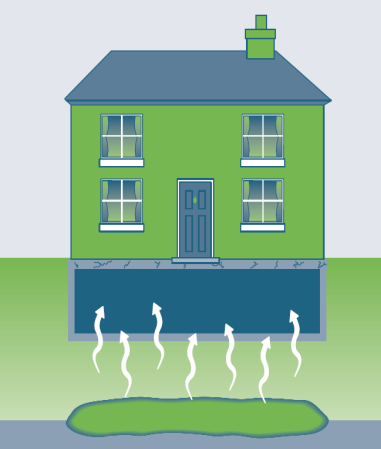
This ITRC Technology Information Sheet provides basic information when using a fan to depressurize the sub-slab environment to mitigate the potential for vapor intrusion at a given building. SSD is the most common engineering control installed in buildings at or near vapor intrusion sites. The operational objective for SSD systems is to create a negative pressure below the building slab. Depressurization occurs when the pressure below the slab is less than that of indoor air. |
Overview
SSD uses an electric fan to create a pressure gradient across the subgrade portion of the building to mitigate the potential for vapor intrusion from the subsurface into the building. When a negative pressure is present within the building envelope relative to surrounding soil, advective gas flow from the soil into the indoor air can occur. Soil gas entry pathways can be cracks through the slab or wall(s), improperly sealed utilities, etc. Depressurizing the soils below the slab with an SSD system will create a low pressure that reverses or alters the direction of soil gas flow, thus mitigating vapor intrusion. The types of fans/blowers used for SSD can vary depending on sub-slab material permeability, as well as the building type, construction quality, and size of the building being mitigated. SSD may be limited to the portion of the floor slab where volatile organic compounds (VOC) vapor concentrations exceed generic or building-specific screening action levels for VI.
General Design
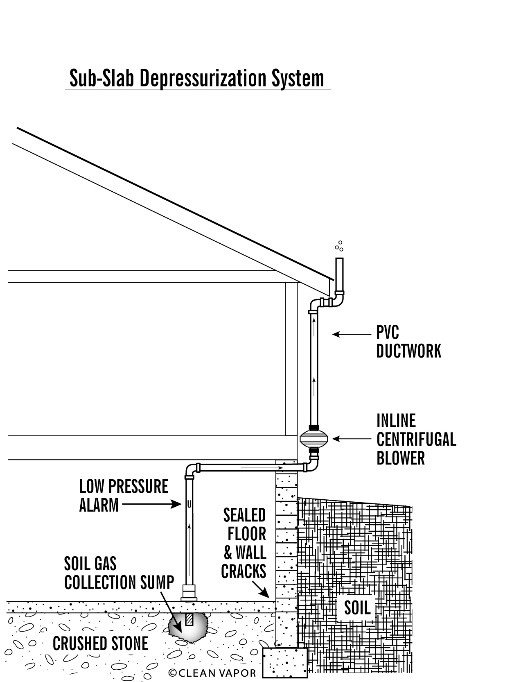
Source: Clean Vapor, LLC, adapted from EPA (1993)
SSD suction points can be constructed by coring through the slab or foundation, trenching in the slab, directional drilling from outside the building, or other methods of accessing the sub-slab soil. Typical system schematics are shown in Figures 1 and 2. Most commonly, a vertical pipe of 3- to 6-inch nominal diameter is installed through a cored hole in the floor. A suction pit or cavity is created below the floor by removing approximately 1 cubic foot of soil or fill material to reduce resistance to flow and enhance vacuum propagation. The piping is sealed to the slab or foundation at the connection point with the cavity using durable caulking or air-tight pipe fittings. The permeability of the subgrade soils and the presence of cracks and openings in the building floor slab will affect the performance of the SSD. Best performance is obtained when the suction pit is left open (and not backfilled with stone or other material) and cracks/openings in the floor are sealed. Practitioners should understand vacuum, air flow, pressure differential(s), and the effects each has on the system design and operation.
Detailed design specifications for design and construction of SSD systems are beyond the scope of this technology information sheet, but information regarding design and operation can be found from the American Association of Radon Scientists and Technologists (AARST, 2017) and the Environmental Security Technology Certification Program (ESTCP) (McAlary et al., 2018). The ANSI/AARST standards are consensus-based standards by which certified installers of radon and soil gas mitigation systems in new buildings may be held accountable. ESTCP resources provide technical information that can inform mitigation system design and operation.
New Building Design
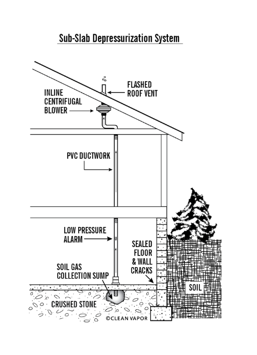
Source: Clean Vapor, LLC, adapted from EPA (1993), used with permission.
SSD can also be incorporated into the design and construction of a new building. The radon mitigation industry has a long history of using radon-resistant construction techniques (USEPA, 1994) (summarized in https://www.epa.gov/radon/radon-resistant-construction-basics-and-techniques), which may also be appropriate for mitigation of the VI pathway for VOCs. These techniques include installation of some or all of the following: a permeable sub-base (or aerated slab with drainage mat or specialized forms), perforated collection piping, construction-grade geomembrane, solid riser piping (extending above the roofline of the building to an appropriate discharge location), sub-slab probes or tubing run to exterior weatherproof box to monitor sub-slab concentrations from outside as a substitute, and accommodations (i.e., electrical connections) for future fan installation. For new construction, a passive fan (e.g., wind-driven turbine) may not be installed initially, but accommodations should be made for fan installation if required in the future.
The need for installation of a fan and operation of the SSD system in a newly constructed building is often assessed and determined by postconstruction air and vapor sampling and analysis. Other options, depending on regulator acceptance, may include:
- temporary operation of active mitigation, which may consist of running the system as a pilot test (e.g., attaching a wet/dry vacuum or temporary fan to a riser pipe), in combination with the sampling and analysis of the vapor extracted from below the constructed building. The vapor concentrations, along with system performance data, are used to assess the need for active operation of the system (McAlary et al., 2018).
- Collection of sub-slab vapor samples prior to venting after the riser pipes have been capped for a minimum of 30 days (NJDEP, 2018), the building is constructed, and the heating, ventilation, and air conditioning (HVAC) system is operational. Capping the riser pipe(s) simulates “worst-case” conditions because some air exchange occurs by passive venting when the riser pipe(s) are open.
If active mitigation is determined to be necessary for new construction, in-line fan(s) can then be installed on the exterior system piping or interior piping that is outside the heated/occupied building envelope. Vacuum influence is then measured at sub-slab monitoring points (located centrally and at the remote extents), and these data, combined with flow rates, mass removal rates tracer tests, and/or other lines of evidence, may demonstrate system effectiveness. A detailed design standard used for radon mitigation that is applicable to active mitigation system design and operation for VOCs can be found in the ANSI/AARST CC-1000-2018 (AARST, 2018c). Additional information is posted by USEPA (USEPA, 1994). A benefit of including a roughed-in active SSD system during new construction is lower cost compared to a retrofit. Also, a highly transmissive sub-floor, in combination with SSD, requires less reliance on the performance of a resistive layer (i.e., a concrete floor and/or vapor membrane).
Membranes Used with SSD Active Mitigation
Although membranes are not typically installed with an SSD system for an existing structure, installation of a membrane should be considered when SSD is implemented during new construction. The thickness and type of membrane selected and installed will depend on soil vapor VOC concentrations, design objectives, and construction logistics.
Vapor membranes can reduce leakage across the floor, which enables the vacuum field to propagate farther and with less applied force (and less electricity consumption) than in cases where the concrete slab alone is the barrier reducing long-term operation costs. The inclusion of a membrane may also provide some protection in the event that the fan(s) are not operational.
For newly constructed buildings where lower VOC concentrations are expected to be present in sub-slab soil gas, a relatively thin membrane consistent with radon mitigation practice may be considered for active systems. For reference, membranes for use with radon systems are specified in the ANSI/AARST Standard for New Construction (AARST, 2020) and ASTM International (ASTM, 2017). The standards for radon commonly call for a membrane (typically reinforced polyethylene or polyolefin) with a thickness between 6 and 15 mils. Caution should be applied in the selection of liners with thicknesses of 10 mils or less because they may be prone to damage during the construction process and are difficult with which to achieve a reliable seal. Additionally, the interaction with VOCs with the membrane will need to be considered. Installation of the vapor membrane should include sealing at seams, pipes, and other penetrations, and sealing to the perimeter stem wall using sealants compatible with the selected membrane (AARST, 2018a).
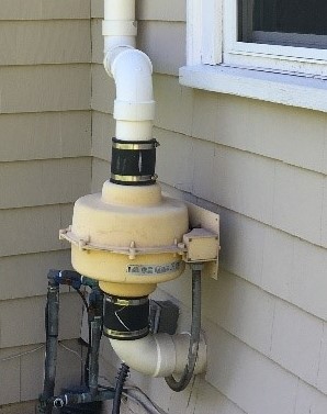
Source: C. Regan, ERM
For newly constructed buildings where higher VOC concentrations are expected be present in the sub-slab soil gas, installation of a more robust membrane should be considered for active systems. Soil vapor VOC concentrations may be considered high when concentrations are an order of magnitude or higher than an applicable sub-slab screening level. A more robust membrane would include products that are more resistant to diffusion of site-related VOCs (e.g., seamed, sheet-applied membranes that are installed with documented quality control procedures). More information can be found on those types of liners in the Passive Mitigation Approaches for Vapor Intrusion Mitigation Fact Sheet and associated supporting technology information sheets.
Components
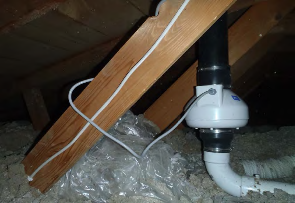
Active SSD technology requires an electric fan/blower connected via piping to the space directly below the floor slab. The electric fan/blower can be installed on either the outside (Figure 1 and Figure 3) or inside (Figure 2 and Figure 4) of a building, depending on locations available.
Source: Clean Vapor, LLC
Typically, fans are installed on the outside of the building due to access issues both for system installation and for ongoing system operation, maintenance, and monitoring (OM&M). Fans installed on the outside of a building are subject to changing weather conditions and, depending on the geographic region, this may cause condensate issues and/or additional wear on the fan. Fans installed in interior spaces (for example, attics) must be fully excluded from occupied and/or insulated interior spaces (i.e., fans need to be located outside the occupiable building envelope) to mitigate the potential for leaks in the fan’s vent from entering the occupied space. Fans installed in weather-protected spaces such as attics have a longer and more consistent operating life because they are protected from extreme weather conditions, but also require permission from and coordination with the property owner to obtain access for each OM&M visit.
The vent pipe from the fan/blower is exhausted above the roofline and away from building openings to avoid re-entrainment of exhausted vapors (AARST, 2017). Optional components depending on operational and regulatory considerations include vapor-liquid separators or moisture knockout tanks upstream of blowers to manage significant entrained liquids and air emissions treatment (i.e., activated carbon) downstream of blowers.
Source: R. Saari, Arcadis, used with permission.
Other features typical of an active SSD include:
- system piping, including a sampling port for conducting system diagnostic testing (i.e., vacuum and air velocity/flow) and for collecting samples to measure VOC concentrations in the effluent in support of sub-slab vapor flux calculations, if desired
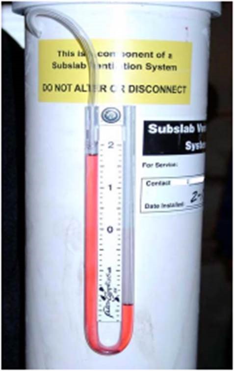
- permanent u-tube manometer (Figure 5), vacuum gauge, or pressure sensor on the system piping to monitor system pressures
- balancing valves on the system piping, which provide an efficient way to adjust system flow from multiple suction points, to account for increased pressure gradients due to drying out of the subsurface soils, and/or to reconfigure the system footprint as sub-slab vapor concentrations diminish over time. Blowers that have variable speeds may also be used to balance or rebalance a system over its operational life.
Advantages
SSD as an active mitigation technology has the following advantages:
- SSD is an easily deployable engineering control that is often considered the most reliable and protective mitigation method.
- Performance can be reliably monitored by measuring sub-slab pressure differential at central and remote extents, reducing the need for expensive sampling during OM&M.
- Continuous performance can be reliably monitored through telemetry connected to sub-slab monitoring point(s).
- SSD systems mitigate vapors from entering indoor air rather than relying on dilution or filtering of the vapors after they have entered indoor air.
- In-line fans, which can be used in most buildings with small footprints or higher permeability sub-slab soils, use a small amount of electricity and require no routine maintenance; therefore, OM&M costs are low.
- Systems are designed to minimize the disturbance/removal of indoor air; therefore, these SSD systems have a low impact on heating and cooling costs.
- Systems can also protect buildings from radon gas and reduce moisture levels in damp basements.
- SSD systems can be implemented on most building types, including existing and new construction, residential homes, and larger commercial and industrial buildings.
Limitations
SSD as an active mitigation technology has the following limitations:
- Installation of SSD systems impacts the occupants of the building in that coordination with and cooperation of the building occupants is needed during system installation (for existing buildings) and ongoing OM&M (both new construction and existing buildings).
- SSD systems will not be continuously effective during high water table conditions where groundwater is in contact with the slab or within inches of the slab and occupies the pore spaces in the permeable subgrade materials.
- Low permeability soils below the slab negatively affect the pressure radius of influence, requiring the installation of additional suction points and/or use of higher vacuum fans.
- Poor concrete slab construction, excessive cracks in the slab, or utility penetrations/floor drains/pipes may create short circuiting of air flow and potentially have a high energy penalty through loss of conditioned indoor air to the sub-slab. A substantial amount of sealing to limit indoor air from being drawn into the system and to enable overall system effectiveness may therefore be needed. Sealants may require OM&M as well.
- High permeability soils below the slab may not allow measurement of large negative pressure differentials away from a suction point(s), providing a false indication that the system is not working.
- SSD systems may not meet performance requirements when required design and construction practices are not followed. Important differences in mitigation design, treatment of exhaust, and practitioner qualifications for VOC and radon VI mitigation should be recognized and accounted for to achieve effective project implementation.
- Installation of vapor exhaust controls may be necessary depending on the VOC concentrations in the subsurface, site type, and/or state air permitting regulations. Installation of these controls may require the use of more robust blower systems, air permitting, and additional OM&M requirements for discharge monitoring and media changeout.
- For some properties, it may be difficult to prevent property owners from tampering with and possibly damaging system components.
- SSD systems will not necessarily prevent diffusion of VOCs across slabs and some vapor barriers if very high concentrations (e.g., millions of µg/m3) are present immediately below the slab. This condition is more likely to occur at existing buildings where solvent-impacted soils are present immediately below the slab and is less likely to occur in new construction where clean materials (e.g., gravel) are placed below the slab.
- Sub-slab utilities, pipes, or drains may result in “short circuiting” or preferential pathways that may reduce the system radius of influence.
Cost Considerations
The primary factors that affect the overall cost of an active SSD system include whether an existing or new building is mitigated, building size, building height, building use, tightness of the soils, depth to water, building HVAC, condition of the slab, number of building additions, size and total number of blowers or fans, permitting, exhaust control (if required), remote monitoring, and OM&M.
Approximate costs for this technology generally range from $4 to $9 per square foot (this range applies to both existing and new building mitigation). These costs are typically for installation only and do not necessarily include the costs of predesign testing; preparation of a work plan, design and specifications; installation monitoring; regulatory agency and stakeholder liaising; post-installation verification testing; and reporting. Additional cost factors may include but are not limited to the following:
- sub-slab vacuum field extension
- the number of suction points
- type and number of blowers
- electrical requirements
- building construction features
- aesthetic considerations
- exhaust filtration
- permitting, regulatory, and legal oversight
A large open building with permeable sub-slab fill material and a concrete slab with good integrity would be on the lower end of the per square foot cost range, while a residential home with a low-clearance, exposed-soil crawlspace, stone foundation, and water intrusion issues would be on the upper end of the per square foot cost range.
Special Circumstances
Special circumstances for construction of an SSD include:
- Insulation incorporating heat trace cable may be warranted to prevent freezing of condensate in cold climates or to dampen noise.
- High water tables or perched water where water is present directly beneath the building slab may require additional measures to achieve SSD system performance objectives.
- If there is high air flow below the building, the technology implemented may be fully or partially sub-slab ventilation (SSV; see also SSV Technology Information Sheet) rather than SSD. Although SSV can be as effective as SSD, there are different factors to consider when determining the efficacy of venting versus depressurization.
- Qualified personnel should conduct design, installation, and OM&M of control systems.
- Precautions should be taken to ensure that new tenants and/or construction activities (e.g., sub-slab utilities, service pits) do not damage the SSD system.
Occupant, Community, and Stakeholder Considerations
It is essential to develop and implement a site-specific community involvement plan that addresses, among other things, how to win trust and gain access to properties, communicate risk to potentially exposed individuals, and minimize the disruption of people’s lives and businesses. The ITRC fact sheet on Public Outreach During Vapor Intrusion Mitigation provides additional information.
References and Resources
Related Documents:
- ITRC Technical and Regulatory Guidance Document, Vapor Intrusion – A Practical Guideline, 2007.
- ITRC Petroleum Vapor Intrusion, Fundamentals of Screening, Investigation and Management, 2014.
- New Jersey Department of Environmental Protection. 2018. VI Technical Guidance. January.
- Soil Gas Mitigation Standards for Existing Homes, 2017, AARST Consortium on National Radon Standards, ANSI/AARST SGM-SF 2017.
- Soil Gas Control Systems in New Construction of Buildings. 2018. AARST Consortium on National Radon Standards, ANSI/AARST CC-1000-2018.
- US EPA 402-R-93-078 Radon Mitigation Standard (revised 04-01-1994)
Related Links:
For more information and useful links about VI pathways and mitigation technologies, go to http://www.itrcweb.org .

[email protected], 919-707-8279 Matthew Williams, Michigan Dept. of Environment, Great Lakes, and Energy [email protected], 517-881-8641 |
Click here to view a PDF version of this Tech Sheet.


