This ITRC Technology Information Sheet provides a general description of aerated floor VSS and their use as a vapor intrusion (VI) mitigation method. Aerated floor VSS are a design component for sub-slab ventilation (SSV) or sub-slab depressurization (SSD) systems. Included is an overview of the aerated floor VSS, conditions for applicability as a VI mitigation method, and advantages and limitations of utilizing aerated floor VSS. An approximate cost of the aerated floor VSS and a list of additional resources are also provided. |
Overview
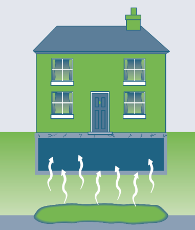
Aerated floor VSS are concrete slabs installed with a continuous void space under the slab that can be used for sub-slab venting or depressurization in lieu of the sand or gravel venting layer commonly associated with traditional mitigation systems. Because the void space has very low resistance to air flow, vacuum levels and air exchange rates in the void space are generally higher and more uniform than in sand or gravel layers. Aerated floors can be constructed in various ways, including open void spaces below structural slabs and permeable geocomposite in place of gravel, but are more typically constructed using proprietary plastic forms that are placed on the subgrade prior to pouring of the concrete slab. Therefore, this Technology Information Sheet will focus on proprietary concrete forming systems that create a void network below a slab.
Aerated floor VSS are most applicable to new construction, although aerated floors can also be used for complete floor replacement or placed over existing slabs if a higher finished floor elevation can be accommodated. Aerated floor VSS are appropriate for residential, commercial, institutional, and industrial building designs.
Proprietary forms typically shape the bottom of the concrete slab to create a network of interconnected dome shapes. The slabs are supported at the points between the domes (i.e., where the concrete contacts the ground) but can also be constructed as fully structural, post-tensioned slabs. The forms vary in height from about 2 inches to 30 inches but are most commonly approximately 10 inches high. Welded-wire mesh is typically placed over the forms for reinforcement, and the concrete thickness above the top of the forms is typically 2.5–3 inches for residential buildings and 5–7 inches for commercial buildings. The slab thickness can be increased to support larger loads as necessary. The domes create an orthogonal grid of arches in the bottom surface of the slab that distribute loads and place the slab under compression; as a result, the volume of concrete is similar to, or may be less than, the volume of concrete required for a traditional flat slab with the same load capacity.
For VI mitigation, aerated floor VSS can be designed for SSV or SSD operation (in the former case, air inlets are typically provided to increase air flow rates) and operated in either active and passive venting modes, depending on the degree of venting or depressurization needed to mitigate VI. Long-term operation, maintenance, and monitoring (OM&M) costs are lower than for traditional mitigation systems constructed with gravel venting layers, because fewer and/or smaller fans are required to depressurize and/or vent the void space. In addition, the vacuum level in an aerated floor is generally higher than in gravel and is relatively uniform across the slab. As a result, confirming and monitoring performance of aerated floor SSD systems is simpler and less expensive than
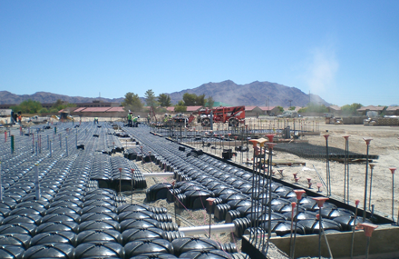
Cupolex aerated floor void space system.
Source: ITRC PVI-1 Guidance Document, used with permission.
for SSD systems installed in gravel. In addition, mitigation systems using aerated floor VSS require fewer riser pipes, relative to an equivalent traditional (i.e., gravel) approach, to remove subsurface vapors. Because aerated floor VSS allow air to directly contact the subgrade below slabs, this technology can enhance oxygen levels and may promote increased aerobic biodegradation of petroleum hydrocarbons.
Components
Aerated floor VSS are generally divided into the following components:
- proprietary plastic forms (various types based on function)
- concrete and reinforcement (placed over plastic forms, as required by structural design)
- riser pipes, inlet pipes, and monitoring ports (as required by the venting design)
- boots installed around all penetrations (similar to boots used for sheet membrane liners)
- caulking/sealing of perimeter and control joints
Advantages
Advantages of using aerated floor VSS for SSV and SSD include:
- higher air flow rates for SSV, and higher and more uniform vacuum levels for SSD than typical sand/gravel venting media
- lower operating costs due to the very low resistance to air flow
- lower costs for system installation due to elimination of gravel layer, sub-slab gas collection pipes, and liner (note: the costs for concrete, steel, and imported fill may also be reduced.)
- relatively quick assembly and installation when compared with the time required for gravel and liner placement
- a single small (e.g., 20-watt) fan can typically provide a relatively high (0.1” water column or greater) and uniform vacuum across buildings up to 20,000 square feet
- separate vapor or moisture barrier not required in most cases due to the presence of the void space and plastic forms when combined with booting and sealing of penetrations through the floor and caulking of perimeter joints.
- useful for mitigating existing buildings with high water table conditions that prevent depressurization under the existing floor slab
Limitations
Limitations of using aerated floor VSS include:
- less use and familiarity in the United States relative to other countries
- less applicable to existing buildings, unless replacing the existing floor slab or placement over the existing floor slab is acceptable
- might not be sufficient when vapor concentrations are high and buildings are negatively pressurized (potentially requiring active venting)
- may increase cost in some circumstances if additional site grading is required to accommodate the void form thickness.
- unfamiliar to many architects, engineers, regulators, and contractors
Cost Considerations
The cost for supply, delivery, and installation of the proprietary forms required for a typical aerated floor system with new construction is typically $2–$3 per square foot, depending on factors such as the size and location of the building. Estimated costs do not include any additional protective barriers, to the extent required by regulatory agencies, or construction overlays ($2–$4 per square foot), although this is not anticipated through normal construction practices. The cost for riser pipes will be lower than for traditional gravel mitigation systems, all else being equal. If the passive mitigation system is upgraded to active, the addition of fans would represent an extra cost. The cost for operation and maintenance would be lower than a traditional (gravel/membrane) system due to smaller or fewer fans. Typically, monitoring costs savings (per square foot of building area) will be greater as building size increases. Costs may differ when retrofitting existing buildings.
Occupant, Community, and Stakeholder Considerations
It is essential to develop and implement a site-specific community involvement plan that addresses, among other things, how to win trust and gain access to properties, communicate risk to potentially exposed individuals, and minimize the disruption of people’s lives and businesses. For more details, see the ITRC Public Outreach During Vapor Intrusion Mitigation Fact Sheet.
Resources
Related ITRC Documents:
- ITRC (Interstate Technology & Regulatory Council). 2014. Petroleum Vapor Intrusion: Fundamentals of Screening, Investigation, and Management. PVI-1. Washington, D.C.: Interstate Technology & Regulatory Council, Petroleum Vapor Intrusion Team. http://itrcweb.org/PetroleumVI-Guidance.
Related Links:
- Pontarolo Engineering. Venting System Design Guide. Las Vegas, NV https://cupolex.ca/downloads/Technical%20Reports/Cupolex%20VI%20Venting%20Design%20Procedure.pdf
For more information and useful links about VI pathways and mitigation technologies, go to http://www.itrcweb.org .

[email protected], 919-707-8279 Matthew Williams, Michigan Dept. of Environment, Great Lakes, and Energy [email protected], 517-881-8641 |
Click here to view a PDF version of this Tech Sheet.

